DIN Rail Energy Meter
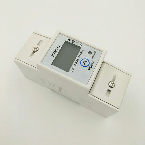
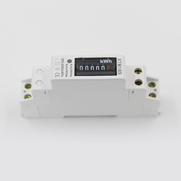
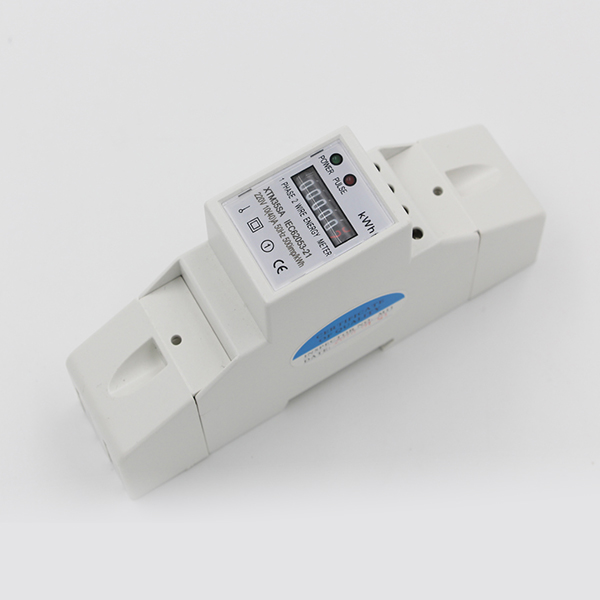
XTM015 Single Phase DIN-rail Energy Meter
DIN Rail Single Phase Electronic Energy Meter
User manual
1. Characteristics and Range of application:
The DIN rail single phase electronic energy meter is a kind of newstyle single phase whole electronic type meter, and adopt up to datemicro-electronics technique and imported special large scale integratecircuit, use advanced technique of digital sampling technique and SMTtechnics etc.
The meters are completely conformed to the relativerequirements of the National Standard GB/T17215.321-2008 andInternational Standard IEC62053-21 on the meter (Class 1).
The meter is used for measuring active energy power consumptionin a rated frequency of 50Hz or 60Hz . It can accurately and directly measure active energyconsumption from positive and reverse directions. It has followingfeatures: Good reliability, small volume, light weight, specious niceappearance, advanced technics.
The meter is installed indoors. The site conditions shall beassumed as follows: The ambient temperature is -25 ~ +55℃, relativehumidity is not more than 95%. There isn’t heavy corrosive gas or anyinfluence of dust, mold and insects etc.
2. Installation and usage:
2.1 The meter can be installed and used after being test and sealed.Without sealed or storage time is too long the meter must be retesting.
2.2 When take out the meters from original packing, if the inner packingor meter cover is found broken, then do not install the meter, pleasecontact company technical service dept.
2.3 Only experienced electrician or professional technician can installthe meter, and confirm to read through the User Manual.
2.4 The meter must be installed ventilate and arid place, the meter baseboard must be on the wall of fire resistance and uneasily shaking.
2.5 The meter must be installed in the protective box in the dusty placeor against possible mechanical damage.
2.6 Connecting must accord with meter case body connecting or theconnecting drawing of the Usage Manual. Commend to use soft brasswires to input to avoid that the meter shall be burnt due to loosecontact.
2.7 When the meter is connected in the electricity net rightly, the meterpower indication light should be bright up.
2.8 In the too much thunderstorm place to adopt measures to avoid thelighting damage.
2.9 The load capacity of the meter is between 0.05Ib~Imax. If thecapacity exceeds above the register shall not be accurate or the currentcoil shall be heated and burnt.
2.10 Data display:the meter have two rows of display,the first row shows electricity is can be cleared,press the “RESET”button on the front panel 3~5 seconds is can to zero,second row shows total electricity is do not reset.
2.11 Impulse indication: When connecting meter load using energy, theimpulse indicator light twinkle display (Lighting about 80ms).
2.12 Reverse direction indication: When connecting meter load isreverse direction using energy, reverse direction indicator light will belighten.
3. Outer and connection drawing:
3.1 Outer drawing

3.2 Connection drawing

4. Test mode:
The meter has energy impulse output port, it locates in terminal 23 andterminal 24.
5. Transport and storage:
4.1 Transport and storage of the meter must not be shaken and mustaccord with ZBY002-81.
4.2 The meter must be stored in the original packing box and theenvironmental temperature is in -35℃~+65℃. Relative humidity shallnot exceed 95%. And there isn’t any corrosive gas. The environmental
temperature shall not vary violently.
4.3 The meters should be in the original packing box and the boxesshould be piled up no more than five on the rack. The separate meter isnot suitable for storage.
6. Deadline of guarantee:
Within 18 months from the date of manufacture the user complieswith all of above rules. If the meter still being sealed does not conformto any technical requirements of IEC62053-21 & GB/T17215.321-2008,
or of any certification of Power Department or Measuring Department,the manufacturer guarantees to repair freely or to replace it.
